
Oil and gas companies require precise measurement and adherence to strict guidelines in order to accurately report the volumes of oil and gas products that they produce. The production accountants tasked with reporting these volumes require accurate and current information from the field (operations) to do this. One important tool that is used by both operations and production accounting to accomplish this is the measurement or metering schematic.
About Measurement Schematics
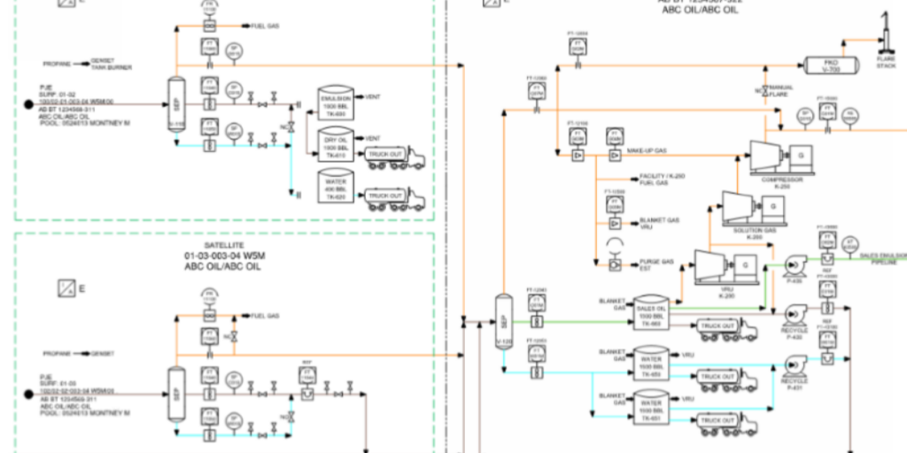
A measurement schematic is a visual tool that shows the flow of production from the wellhead to sales or disposal. It shows flow from left to right and shows all related equipment at each location.
See Figure 1 below for an example of a measurement schematic:
Measurement schematics are required for all active facilities. There is no grandfathering for any active facilities. Schematics for reactivated facilities must be up to date within three months of reactivation or after the implementation period, whichever is later.
Operators must provide measurement schematics to the following third parties upon request:
- Licensee of the subject facility.
- Company performing the volumetric reporting for the facility.
- Company that performs the product and residue gas allocations up to the allocation point(s).
- The AER or other Alberta or cross-border regulatory bodies.
- Operator of receipt/disposition points – all reporting measurement points for the facility only.
Measurement schematics have a number of requirements to align with Directive 017. These include:
- Facility name, facility licensee name and operator name if different.
- Legal survey location (LSL) of surface facility and UWI, including downhole location if different.
- Facility boundaries between each reporting facility with associated Petrinex codes and subtypes.
- Flow lines with flow direction that move fluids in and out of the facility and those that connect the essential process equipment within the facility, including recycle lines and bypasses to measurement equipment. Identify if oil is tied into a gas system.
- Flow split or diversion points (headers) with LSL if not on a well or facility lease site.
- Process equipment that changes the state or composition of the fluid(s) within the facility such as separators, treaters, dehydrators, compressors, sweetening and refridge units etc.
- Measurement points and storage tanks or vessels that are used for estimating, accounting or reporting purposes, including:
- type of measurement (meter, weight scale or gauge)
- Type of instrumentation (charts, EFM or readouts)
- Types of meters if applicable
- Testing or proving taps required by the AER
- Fuel, flare or vent take-off points – default to estimated if meter not shown.
- Energy source (gas, propane, electricity) used for equipment if not measured or estimated as part of total site fuel.
- Permanent flare points.
- Freshwater sources such as lakes or rivers.
Required information for wells:
- Include
- all producing, water source, injection/disposal and shut-in wells
- reporting event for wells with downhole commingled zones
- Identify
mechanical lift such as plunger lift, pumpjack etc
- in Alberta default to well status of FLOW if not shown
- in Saskatchewan default to well status of ACTIVE if not shown
- in British Columbia default to well status of Active if not shown
- Suspended wells are optional; if shown identify them as suspended
Required information for process equipment:
- Include normally closed valves that can change production flow.
- For
compressors identify if electric or gas drive.
- If gas drive, then the horsepower or kilowatt rating is required unless fuel gas is measured as part of total fuel within a facility. Some cross-border facilities may be required to measure fuel for some compressors individually.
- Normally open valves such as emergency shutdown valves (ESDs), pressure-control valves and block valves are not required as they can be considered default flow.
- Pressure safety valves are not required.
Measurement point requirements:
- Identify non-accounting meters if shown.
- Originating facility ID or UWI/LSL for truck-in receipt points is not required.
Storage tanks and vessels requirements:
- Include for these tanks, vessels and caverns fluid type (eg. oil, emulsion, condensate, plant product, waste or water); tank and vessel capacity may be shown on a separate document and should be available upon request.
- Identify if the tank or vessel is underground or default to aboveground.
- Identify optional non-reporting chemical storage or pop tanks if shown.
- Identify if the tank or vessel is tied into a vapour recovery system (VRU) or flare system.
Measurement, Accounting and Reporting Plan for Thermal In Situ Oil Sand Schemes (MARP):
- Include:
- Blowdown lines
- Ponds – volume and fluid type
- Meter ID and sample point ID
- Tank gauge
- Pumps
- Secondary measurement points
Physical Changes to Locations & Equipment
When there are physical changes to locations or equipment that affect reporting they must be captured on the measurement schematic when they happen. These changes must be communicated with production accounting immediately so that Petrinex reporting for the current period will be correct.
Physical changes such as wells being added, suspended or shut in, piping changes, or equipment changes require an update. Temporary changes within the same reporting period don’t require an update to the measurement schematic.
Measurement Schematic Master Copy
The master copy of the measurement schematic must be updated at least once per year to reflect any changes. Verification of the revisions is required (also verification if there were no changes). If verification of revisions is not on the measurement schematic it must be available upon request.

Exceptions for updates can be found in AER Directive 017 Section 1.9.2.
AER Directives 007 and 017 as well as Manual 011 contain the rules for delineation of lease sites and geographic areas into reporting facilities.
As multiple measurement points as well as regulatory flexibility can result in more than one way of delineating some facilities, follow these guidelines:
- All gas and liquid received at and delivered from a facility must be continuously or batch measured in a single phase.
- Wells
and associated equipment are only linked to and reported under batteries or
injection facilities.
- Gas wells must be linked to and reported under gas batteries.
- Crude oil/bitumen wells must be linked to and reported under crude oil/bitumen batteries.
- Disposal wells must be linked to and reported under disposal facilities.
- Injection wells are linked to and reported under injection facilities.
- Source
water wells can be linked to a battery but are more commonly linked to the
injection facility.
- If there is gas production link to a subtype 902 battery to facilitate gas production reporting.
- Measured
and prorated wells should not be linked to the same battery.
- Report under separate reporting codes.
- Facilities using either regenerative sweetening processes or hydrocarbon liquid recovery processes must be reported as gas plants if the produce greater than 2.0 m3/d of hydrocarbon liquid.
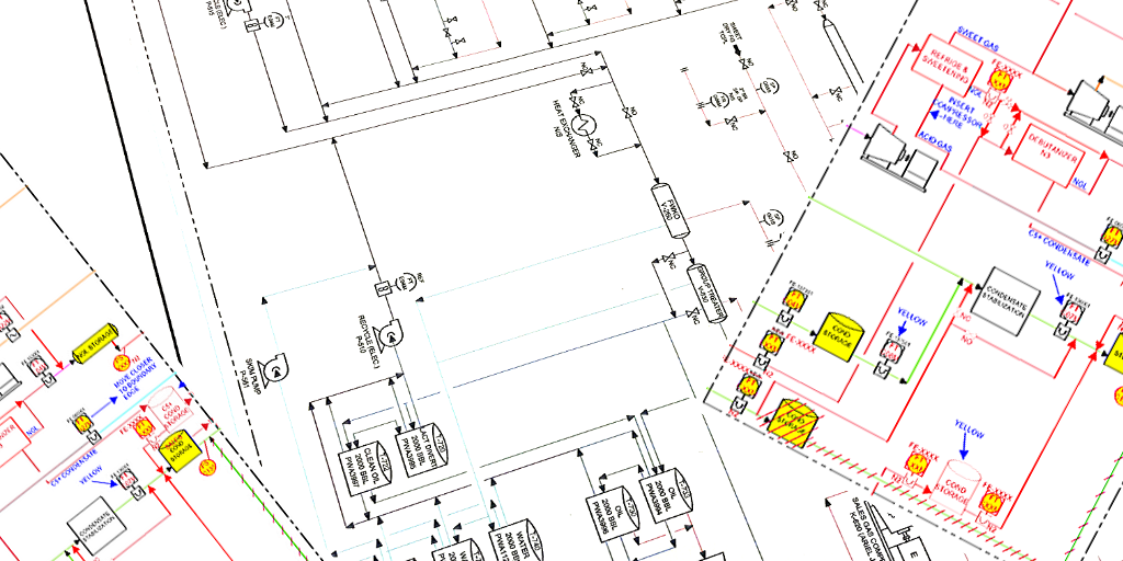
Production accounting departments are often located in offices far removed from operations. Because of this fact, it is essential that information from the field is correctly captured so that all stakeholders can produce accurate results. When operations ensures that any changes from the field are quickly added to the schematic it allows production accounting and field data capture systems to be kept up to date. This will ensure accurate reporting and compliance with Directive 017.
See Figure 2 for an example of an existing schematic marked up with redlines (updates) from operations.

About the Author
Chris Terry is a Measurement Specialist and Journeyman Instrument Technician at Intricate; a Canadian energy services provider. Chris has been with Intricate for 8 years and graduated from NAIT’s Instrumentation Engineering Technology program.
Sources: AER Directive 017